
A great PRT design should squarely address forward
compatibility and extensibility. These are two distinct, although related,
concepts. To be forward compatible a
current system must be designed to gracefully interact with future versions of
itself. This is extremely important with PRT because the track or guideway will
generally become a permanent piece of infrastructure whose design should
support any conceivable future vehicle improvements.
Extensibility is somewhat different. It is the ability of a
system to be adapted to whole new uses. An example for PRT would be to use the
system to deliver freight. Designing to be extensible is a whole different
challenge because it tends to conflict with the optimization of a system for
the original purpose. Nevertheless it certainly seems silly to foreclose future
functionality through design decisions that might otherwise be completely
arbitrary.
Some current PRT offerings seem to have been forced, presumably
by financial restraints, to curtail design features that would enhance forward
compatibility and extensibility. It remains to be seen whether this strategy
helps PRT adoption or actually hurts it by limiting the flexibility needed to
address a city’s varying needs.
One example of this, which we will examine here, is the off-line
station paradigm, which has become an assumed characteristic of PRT. This
notion presupposes a number of issues, most notably a steady flow of would-be
riders at every station site. One of the strengths of PRT is that it does not
rely on aggregating passengers to fill large vehicles. This advantage is traded
away, however, when the cumulative cost of feeder track and an elevated station
effectively means that it must be busy at all times to pay for itself. This
requires a pedestrian density that typically won’t be found throughout the
city. Yet PRT is envisioned as a distributed network – one that only realizes
its full promise with large geographical reach and many stations. If you have
already grouped people together, and you are sending them all to one of only a
few destinations, what is the point of doing it in individualized vehicles?
Sure, the individualized vehicles make the system extensible…just add track.
But does the city’s layout include contiguous station sites with sufficient pedestrian
density to make each station viable?
One idea that I have never seen discussed is to have low speed
loops that serve minor stations, each having only a very short
drive-in-back-out spur. In such an arrangement these loops would act as feeders
for a more conventional route with greater speeds and capacity, similar to the
feeder roads along freeways but looping away to get greater geographical reach.
The regular line would have the more conventional off-line stations. In this
design, which works like a typical residential road where residents back out of
their driveways, vehicles would obviously need to wait their turn, just like
the road-based counterpart. Still, significant local traffic can pass without
this being a significant disruption. The idea would be to keep each loop small
enough to limit traffic to just a few vehicles per minute. This would presumably
be able to service several city blocks in areas where there are no high-rise
buildings to create high peak demand. With a control system that allows
variable vehicle speed, vehicles on such a slow loop can exit at very low
speeds, meaning the spur would be a sharp turnoff, and not a long deceleration ramp.
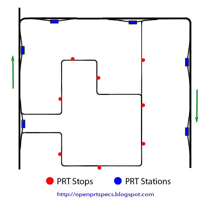
The picture at the top of the page shows how, in a fully 3D
system, a spur can be dropped anywhere. Bus
stops are particularly attractive destination choices, since they come
readymade with seating and at least some sort of cover. The picture below shows
a portion of a traditional PRT loop with low speed track serving the areas
within. In this example there is one way in and two ways out, but there are
probably hundreds of other possible configurations. In this example the same deceleration/acceleration
ramps are used for off-line stations and to access the slow loop.
It should be noted that the low speed track can be
manufactured more cheaply than higher speed track because it can be designed
for greater headway, (less weight) sharper turns, (kept within an easement) can
be designed to never admit heavier vehicles, and would not have as much stress from
vehicle inertia. It would also require less copper because of the scant traffic
load.
To bring this all back to the subjects of extensibility and
forward compatibility, this is an example of designing PRT with both in mind, especially
in the direction of less expense and greater coverage. Larger, heavier or faster
systems will necessarily cost more, and this is what cities are most likely to
seek when there is an immediate, otherwise intractable problem. PRT
configurations need to address these immediate concerns first. But for a long-term,
more comprehensive mobility solution, a more extensive network is needed. Thus there
is a need for extensibility toward the lighter, cheaper track and stations that
could put more areas in reach. On the other side of the coin, in a growing
city, faster, longer range (and maybe even bigger) solutions will be increasingly
needed, so a system should be able to grow into those roles as well.
Clearly, it is less challenging and more straightforward to
simply say, “Here is our vehicle, here is our track, and here is our station,” and
a product that involves a confusing array of choices is hard to introduce into
the marketplace. But the ability of a particular PRT system to evolve and improve
would seem to be an important measure of its worth as well.
2 comments:
The PORT project has a good illustration of low-speed loop advantages (when combined with a cabling system to lower the pods), namely running parallel tracks with crossovers, to allow multiple stops with parking facilities for spare pods.
http://www.overtransit.com/?page=pictures
The parallel track is also useful in high-demand stations, to allow parallel loading/unloading.
For low-speed loops, the lowering facility helps with costs, as stations can be just a landing area. (though the spur you've illustrated is very compact and could be integrated with the track-bearing poles - nice!)
Dan the Blogger Responds -
Sorry for the delay Alexis, my computer has been away from me…
The problem with “artist’s conception” renderings such as these is that they make the viewer believe that certain things are simple and practical which, in fact, may not be. What is misleading here is the weight and/or actual girth of those spindly arms. Because any sideways force, such as wind, has so much leverage when multiplied over the length of the arm, there is bolt-snapping, metal deforming torque at the fixed end. And this mechanism must be designed to be trouble-free and goof-proof for tens of thousands of repetitions. The bottom line is that I can see no way to do this with less than 400 lbs. of metal weight (arms alone) being added per vehicle. Adding weight is a pernicious, circular thing. Add it here and you have to add it there. Add it there and you have to add it somewhere else. For example, there is a significant amount of motor weight required to properly accelerate that extra 400 lbs. It all then gets multiplied times the number of vehicles on a track span, and you have to make that track that much beefier. Soon the entire system cost goes up or you have to reduce passenger capacity. In the US, at least, there essentially no government help and much public resistance to new infrastructure, so all designs must super cheap, slim, and preferably high up. My cabin is already as small as I can go and still comply with US wheelchair laws. By the way, even a decent winch that doesn’t move at a crawl is pretty heavy, and you need a spare, as well as heavy duty mounts and support structure.
I can see three options that make a dropdown cabin more practical. One is using a support pole, like in the “Bubbles and Beams” video. Another is using a combination of carbon fiber (or the like) and triangulated cables to engineer a scissor-lift design that is meant to give and not break or permanently deform. A third is doing something to reduce the distance that is spanned for the average drop. I might add that in regards to the second method, I believe suitable ultra-light cable-stabilized systems are possible, probably using some clever non-square geometry and pulleys… something related to a tensegrity mast, perhaps. Of course my system uses just four pinions per vehicle, probably under 5 lbs. each, period. It also does not preclude drop-down systems if and when they have been sufficiently engineered to be of serious consideration.
Post a Comment