Sunday, June 27, 2010

92> Crack in the Track, Jack...

In my quest for the optimal hanging style PRT track I have found yet two more factors that could influence overall profiles and dimensions. But first, let me offer something to new readers who may not be convinced that PRT is a good idea in the first place.

I recently read a critic of PRT espousing the argument that automated cars would bury PRT because they would not require “new” infrastructure. I’m pretty sure the author hasn’t had his large front yard turned into 2 extra lanes and a median like I have, or he would realize that we are putting in thousands of miles of “new” infrastructure every day. Road construction is so “baked in” to the society that we no longer question or even notice it. I would wager that there isn’t a person in a thousand who has any idea of how much of their own personal money goes into road construction annually. When you find out you just might want to join the Tea Party movement.

More automation is coming to personal transportation. That is for sure. But with the current infrastructure that means trying to automate vehicles on icy roads, amongst texting teenagers and lost, darting pets. What will be the automated vehicle’s response to a downed power line? When it wants to go back to manual mode will the driver be available in time? Or caught looking something up?

Honest acknowledgement of the need for infrastructure that is safer for self-driving cars leads to a healthy debate about what it should be. Do we need it all to be big enough for trucks? Do we want to have to salt and plow it in winter? Do we even want it on the ground? Do we want it to enable fast vehicles or should we just slow down and save fuel? Do we want freeway-like non-stop service? If so, how is this best accomplished? Can we leverage what is already out there, in terms of existing roads and bridges? Should we limit the vehicle size since we know that people, given the chance, will choose obscenely oversized ones? What about the larger debate over urban planning and development?

Yes, we need new infrastructure, and yes, some of it will need to be ordinary roads and bridges. But roads are mostly used for single individuals going to particular destinations, and are, frankly, way overbuilt for this purpose. Even without PRT, it is time to re-examine our infrastructure requirements and consider putting down something that is less wasteful of taxpayer’s money. If we want a cheaper, minimum-footprint, longer lasting transportation infrastructure that is designed for fast, appropriately sized, automated vehicles, then we are basically talking about PRT. PRT is a logical outcome of a very logical debate.


Now on to the picture.  Back in Post 83 I showed a track profile with the actual running surface areas in red. This, as you can see, is that track but in the form of a crossing. Clearly there would be some loss of guidance as a bogey passes through, but not enough to be critical in any way. Also note that the wheels must span a two-inch crack in the track. This weighs into the wheel size debate because a smaller, harder wheel, without a special preventive design, would hit the gap hard, whereas a larger inflated rubber tire would glide right over it.

Such a crossing also raises old debates about “brick-wall” stops and the spacing between vehicles, and reminds me to consider the possibility of a failsafe track-based braking system.

It is reasonable to at least consider such a scheme for PRT because it could make merge and crossing collisions impossible by physically keeping two vehicles from entering the same space. So far I have not even considered how such a system would be designed, but something like a tail-hook comes to mind, which should not influence track profile all that much.

Here’s the second factor that could influence track dimensions. When I was first considering these matters, I recalled the ill-fated involvement of Raytheon in the PRT designs pioneered by Dr. J.E. Anderson. Upon their breakup, Dr. Anderson did extensive public polling and redesigned his track accordingly. I had always thought that Raytheon’s track was ugly and my initial reaction was to simply applaud this new, thinner rail.

I have, however, subsequently come to question some of his conclusions. Specifically, he was designing for the very narrow range of applications that were viewed as most advantageous commercially. In these dense urban environments, there are many factors that make setting supports very costly. Hence he opted to go for long spans, even though it meant relatively costly trusses. Contrast this to the approach taken by Higherway Transport Research. 


This illustration shows a how a track profile very similar to mine can be made by roll-forming a few lengths of steel. This can be done on relatively thick stock, by the way. My books have cold-rolled square tubing with up to half-inch wall thickness. Without critiquing this design specifically, I would just say that it illustrates how more frequent supports can greatly simplify the structural requirements of the track. For long runs, along freeways, for instance, there are no buried utilities, no streets to block during construction, no driveways in the way. A higher amount of track noise is acceptable, and there is less worry about the visual impact. I suspect that cheaper alternatives exist to the long spanning truss designs I have shown. 

All of this opens a larger debate about a factor in support spacing and design that I am not well versed in. That is the matter if regional soil types and the best way to anchor to that ground. In some areas, bedrock is very close to the surface; while in others there is sand or clay many meters down. Would Dr. Anderson have gone for the long spanning trusses if setting supports only involved simple drilling, as would be the case following freeways in most gulf coast cities? If miles of track were required in such a situation, what would the optimal span between supports be? Would many lighter supports be, in the end, more practical? After all, this would limit the weight any single support would have to bear. I still believe the truss design to be very important, in any case, since spanning intersections with multiple lanes requires such a design anyway. Still, I really haven’t considered the ideal freeway following configuration, which would be very important in young Sun-Belt cities like Houston, which have urbanized along the freeways, more than from the city center. 

By the way, Speaking of Higherway… designer and founder Tad Winiecki has an interesting suggestion as to the type of tires to use. (Alert readers will remember my search for a small but heavy-duty, high-speed tire for the tilted wheel motor designs.) He suggested small aircraft tires… I’m looking into it.

Anyway, those are my musings for this week… And so, signing off from somewhere near Crack-in-the-Track, Texas… This is Dan the Blogger, wishing you all a good night!

Sunday, June 20, 2010

91> Dan the Blogger was Writing ...


“Dan The Blogger” was writing a comment (to alert reader Andrew F) and decided to just go ahead and make a post out of it. (I refer to myself in the third person as sort of a joke, as well as a way to be found slightly more easily on the Internet) The comment was about putting utilities in the track, and here are some observations:

Electric companies keep themselves pretty busy repairing electric lines that are damaged by ice, wind, auto accidents, etc. Recently, in Louisville KY, the tail end of a Gulf hurricane darkened much of the city for weeks, and then, a couple of months later, a severe ice storm did the same thing. There was a public outcry. The electric company reported that the only real solution would be to bury the wires, something that they estimated would cost about one million per mile. That was that. The poles remain.

Actually, in spite of the cost, buried lines carry a fairly large percentage of the electricity in the U.S. But the wire is not totally safe there either, and one city reported a digging accident, on average, every single day. There are also problems with water intrusion and corrosion. So what I take away from this is that even with the cost and problems of buried lines, it is still widely considered worth it. They have never dreamed of the kind of sheltered accessibility that the PRT track would provide.

Meanwhile, in San Francisco, a lawsuit was recently filed against the electric company for polluting the ground water. Wooden telephone poles have been treated to prevent rot with a host of nasty chemicals, mostly illegal these days, and are known to leach these poisons into the soil. Millions need replacing annually because of rot, which, if you think about it, is actually the process of the wood itself turning into soil, preservative and all. At some point this practice will stop. Any electric company that would proactively take out the poles and the dirt around them before they were forced to do the job under regulatory scrutiny would be doing their shareholders a big favor. And they would look good doing it.

I wonder then, about the prospect of offering to house a mile of those electric lines safely for a mere, say, $900,000? That’s about $170.00 per ft. enough to pay for all of the steel in the trusses I showed last post. Those poles need to come out eventually. It is just a matter of time, and the contaminated area is expanding as we speak.

Then there is the matter of street lighting. Most streetlights are outdated, by and large, both in electrical efficiency and design. As a person who flies a fair amount, I often stare down in wonderment at the sheer volume of energy used to light all of those city streets below. Although the typical sodium vapor is quite efficient in many respects, LED lighting has the potential to vastly reduce energy costs over all. Apparently, as sodium vapor lamps age, they require high and higher voltage to stay lit, eventually exceeding the capacity of the ballast, and the light will begin to flicker, then flash intermittently, then go out altogether. But another aspect is the whole notion of always flooding a large area with bright light even when it is not needed. You can’t put dimmers on sodium vapor streetlights.

Way back in post 14  I illustrated PRT track based street lighting. It uses many little directed spotlights to illuminate objects on the ground without blinding drivers. When drivers are not forced to stare into the light they need less of it to see, hence less wattage is required. Furthermore, much less light is needed at, say, 3:00 AM than at 10:00 PM, because there is almost no traffic. Having many smaller lights enables energy saving schemes where, for instance, half of the lights are turned off in those wee hours or are on motion detectors. More savings. And of course there is the matter of not needing a ladder truck to change the LEDs, which last longer in the first place.

The point is that the city, too, has a potential financial benefit from PRT track, aside from the transportation angle. By the way, this money is your tax dollars at work. In Los Angeles, for instance, each 50’ property is assessed $70.00 per year to keep those streetlights on. Not only will PRT make a street quieter, (over adding a traffic lane) it could directly save the effected property owners money.

Another aspect is the possibility of using solar cells on top of the track to eliminate the electrical costs altogether. Even amorphous (cheap) solar cells produce about 5 watts per square foot. This means the track could produce, say, 10 watts per linear foot. I would guess that this is pretty close to sufficient for the kind of system I have in mind.

I must say that, as an era, this is not one where the “winds of change” are blowing very hard. Perhaps people are a bit overwhelmed by the pace of advancement in communications and computer related fields. It’s certainly not like the sixties, when every car needed fins and taillights that looked like booster rockets to celebrate our entrĂ©e into the “Space Age”. At any rate, it seems people are in no mood for their government to try anything new with their tax money. Can you imagine mega-projects like the interstate highway system or rural electrification getting passed today? PRT is going to need to be seen as having multiple, tangible, short-term benefits as well as those harder-to-explain ones that most of us already understand. It will need to be structured in a way gauged to gain friends in high places and to have multiple levels of public appeal.

No black outs and tax savings – That’s a start.


Sunday, June 13, 2010

90> Let's Take It From the Top


I want to go back to the beginning in my discussion of PRT track, specifically track for hanging style PRT, for the benefit of the majority of readers who have not followed the ongoing development of the corresponding SMART (Standardized Modular Automatic Rail Transport) specification.

The most fundamental concept that needs to be understood is that of switchless steering. Unlike a railroad, which requires a track segment to be mechanically moved to provide switching, PRT designers have generally agreed that this can be more easily done by the cars themselves by means of engagable/disengagable guide wheels. These require a vertical surface to engage upon. Since the main wheels (or even a Maglev system) require a horizontal running surface, the two, in combination, look something like this.


 It should be noted that only one half of this book-matched arrangement is theoretically needed, except for places where tracks are merging and diverging, though leaving the redundant half in has advantages (load distribution, simplicity of symmetry) which I believe out-weigh the disadvantages. This picture,
from post 54, illustrates the concept.

The second concept is the combining the functions of multiple wheels into one. A look at a roller coaster wheel setup  shows how multiple wheels can hold a vehicle tightly to a track. A simpler approach, however, can be achieved by the use of flanges, as on a train wheel, or dished in or out wheel or track profiles. The angle of contact, though, in such systems, should be as close to a right angle as possible or the flange will tend to wear out, since it introduces a point of friction to the system. A quick look at my older posts will show various examples of radii on both wheels and track.

A third concept is that plate that keeps appearing in my track designs, pictured below.


Whenever a tube-like structure is bent, it tends to flatten out in the process. If a section of track is spanning a great distance and is bearing a great deal of weight, the downward forces will tend to want to flatten, then fold the track under that weight. Stopping this flattening arrests this tendency and strengthens the track. In the case of an encased track with a slot in the bottom, the initial flattening would cause the sides to fold inward or outward, thus narrowing or widening the slot. These plates, placed periodically, prevent this. In the second picture you can see how such bracing can be connected by long plate steel to make a complete box beam. Personally I find this design ugly and worry about single wall designs for PRT because of noise, condensation, and uneven expansion.

A fourth concept is modularity. Almost all discussions on PRT touch on the possibility of movement of goods as well as people, particularly at night. Additionally, many envision a variety of vehicles, and the current diversity of motor vehicles that populate our roadways would tend to bear out the desirability of this approach. Such ideas are not put forth by actual PRT vendors, however, since it currently would be counterproductive for them to develop and offer a confusing array of alternatives. Then there is the matter of routing. Long commuter type routes would call for faster vehicles or possibly vehicles for groups, if there were sufficient numbers of people with common origins/destinations to support this scenario. Therefore there would seem to be a very strong case for creating a track that is compatible for all or any of these vehicle types or speed ranges. This logic leads to a track profile where smaller vehicles are compatible with the track of the largest anticipated vehicle type. I submit that this “largest vehicle” would be GRT. (Group Rapid Transit) In the U.S. many cities have “Park and Ride” systems already in place, which aggregate passengers in outlying suburban locations. I would not want to rule out shuttling in these passengers in groups of, say, 10 or 12. Although GRT is a contentious issue in PRT circles, it should be noted that from a track design point of view, there is very little difference dimensionally between the two. Heavier gauge steel, more frequent supports, or simply spacing heavier vehicles more sparsely are ways to accommodate such a possibility. Whereas PRT track could be made smaller (in profile) than track for GRT, the size of the truss that is required to span reasonable distances can fit either. I would suggest that any such heavier track be used for arterial routes only, because cost is everything when it comes to expanding limited routes into meaningful networks, which, after all, is what PRT is all about. This modular approach recognizes that no one set of engineers is liable have all of the answers as to the very best vehicle design.(s) any time soon. Therefore I suggest removable running surfaces. This has the added advantage of reduced noise, a smoother ride, and essentially no chance of condensation. It also looks to a future with possibilities like Maglev. In order to accommodate the largest number of vehicle types I suggest something like this general shape.

The design allows for several centering means through the use of either convex or concave surfaces. My only concern is the fabrication of this profile, especially radiused sections for turns, because the required roll-forming equipment for that is not universally available on a local basis. Although I have tried to keep my designs easy to produce anywhere, this may be something that would need to be shipped in. I suspect, however, that many local job shops would be happy to fabricate the shape by splitting stock pipe and making curves by a tack-and-bend-as-you-go method.

Although I promised some further thoughts on use of tension cables to extend the span of track sections, I would like to put that off for the moment and return to standard truss design. As far as box trusses go, the round tubular type seems to be acknowledged as the strongest, and was the choice for the Skyweb Express demo track. I believe 90 ft. was the maximum span.

It has the disadvantage, however, of being relatively complicated to fabricate, because the pipe ends must be cut to match a curved surface. (I have seen the tube ends are flattened in some applications) I have wondered about this for some time, as it seems that square tubing would be so much easier, since it just needs to be mitered. Nonetheless, in most demanding situations, such as cranes, these complex joints are almost universally used. Here is a picture showing he complex cut. These have just been tack-welded.


In the illustration below I have taken a similar box truss but substituted those plates for the verticals. Because the plates are only rigid in one direction, I have stiffened them by joining the upper and lower gussets into a single piece. I have also used simple miter cuts on the diagonal pipes, again, using gussets to reinforce the joint. This is not exactly to scale and the diagonal and horizontal pipes don’t even touch in this picture, (much weaker) but this is just a conceptual drawing. The general design should, however, be very strong, cheap and easy to build anywhere where CNC flame-cut plate and pipe is available.


In the next picture the red surfaces indicate the running surfaces for a PRT bogey, taken from Post 83.

If it looks like I haven’t decided exactly what becomes part of the truss and what becomes removable, you’re right! I have not. There’s also a radius missing. It’s a work in progress. Also not shown is the skin, and provisions for electrification, communications, carrying utility wires. There’s plenty of work to do, and now you all know were I stand at the moment. For shorter spans or hanging sections, BTW, the design would be completely different, but, as they say, “One step at a time.”

Tuesday, June 8, 2010

89> On the Road Again...


I am in the civilized world once again. Well almost. The bus I took from Dartmouth to Boston had wi-fi – just no AC receptacles. My poor old laptop only holds a charge for about half an hour these days, so the planned two-hour bloggathon had to be cancelled. That made me wonder what will happen when those upcoming electric cars start stopping on the road for lack of juice. Yeah, I know, they will be have low battery alarms, quick swap battery packs, and there will be charging stations… But that won’t do it.

With gasoline, when your tank is almost empty, you have a certain amount of time to get to a gas station, and it is a fixed amount. A limited amount gasoline will always get you roughly the same distance, even if your car is old. Not so, batteries. When they get old their performance falls off of a cliff. That means that just because a 60% charge got you home with juice to spare 4 months ago, there is no guarantee that a 75% charge will get you home today. Couple this with the high costs of batteries, people struggling to make ends meet, and human nature, and it will be roulette by the masses, with many making shorter and shorter trips, until one day it happens to them, just like it happened to my laptop on the bus. I was almost finished with my research when BOOM! Windooze lived up to its name. Involuntary hibernation. I predict that the only meaningful way to solve this dilemma will be to automatically slow the car down to walking speed before the battery is finally exhausted. That will force people to deal with the problem or at least get them on to the shoulders. Someone should patent that. Oops.

Another thought occurred to me, sitting on that bus. I was considering the effort that was taken to blast away the granite hills to make way for the road. And such a wide swath of land.  I guess the wide median is to make oncoming traffic lights less blinding. And now it will need mowing forever more. It made me consider the hypocrisy of “saving the rainforest” without starting first a little closer to home. When my computer died I was trying to learn a little something about “carbon credits”. The whole concept of paying someone not to burn to offset the burning that you must do would seem to be a concept with some relevance to systems like PRT. I wonder, for instance, about the carbon emissions of a highway, about viewing a given stretch of highway as a CO2 producing system, including factoring in the loss of CO2 sequestering forest that such a system requires. (I wish they could also factor in habitat loss and fragmentation)  Isn’t a highway a bit like a coal burning power plant? What if highway land had to be offset with carbon credits? Thought of in that way, elevated PRT starts looking pretty good.   

As I approached Boston, computer tucked away, I couldn’t help but notice how expressive cars are. These days there doesn’t seem to be much taste for expensive, formal clothes, so that leaves the car as one of the few mobile ways to resister our social status to the world. That’s a very basic primate behavior and not easy to break. And it runs so much deeper than just status. Carmakers can make us feel masculine or feminine, outdoorsy, socially conscious, sophisticated, elegant, fun loving, daring, young, reasonable, powerful. Take your pick. You’ll feel that way and project that self-image to the world. That role is pretty hard to replace with a public transit system. Even one with wi-fi and AC.

Sunday, May 30, 2010

88> Gone Fishin'... sort of...

Sorry folks, I’m without internet and with very limited power, at least for a while. As many of you know, I normally flee the hot climate of Texas in the warmer seasons, when possible. I am in New Hampshire working on ongoing projects that are related to my cabin here. Since my power here is limited to a few solar cells, and I have no internet access, I usually rely on a particular comfy chair at the trusty town library for any computer related activities, including this blog. The problem is that the library is closed for remodeling. If it were a rainy day, I might be inclined to travel a few miles further and make an afternoon or an evening of it at some other library, but work calls me back to Texas soon, and I need to make the most of the good weather and my limited time here.

Sorry about the broken link to the video in the last post. I don’t know why it doesn’t work. If you search YouTube for it, you get the same video at the same address. Go figure. I also apologize for all of the unanswered emails. The library is supposed to be finished in a week, and rain is forecast, so stay tuned!

Sunday, May 23, 2010

87> PRT Track and Bridge Design


I have been trying to devise the absolute best PRT track design I can come up with, with the help of you, the readers. My goal is to offer an alternative transportation infrastructure that beats the pants off of roads by every metric, save for (initially) the network effect. In my opinion, only then will politicians and transit decision-makers have the political cover to move forward with a PRT program.

The search for the best track design brings up some inevitable questions, such as “How far apart can the supports be before the stability or economy of the system is compromised?” and “How high should the track be?”

The first question leads to an examination of bridge design. Trusses with minimal girth, such as Pratt, Howe or Warren trusses) seem to top out at about 100 feet. The most economical way to span long distances, however, lies in the introduction of tension elements, such as is seen in a suspension or cable-stayed bridge. The most extreme case of a tension maximizing (compression minimizing) design would be the cable/tower arrangements that support ski-lift gondolas. Some have proposed such means as an urban transit system, and they certainly would have something there were it not for the need for multiple origins and destinations.

 It would be an easy matter to design a flexible track and simply pull it tight, though sagging in the middle would be both unavoidable and unacceptable. Pulling this sag up with cables would seem to be the cheapest way to span long distances with a minimum profile track. 

 
Suspension Bridges can traverse the longest distances, but cable-stayed bridges (above) offer other advantages. A good explanation of how the two compare is found about halfway down this Wikipedia page. ttp://en.wikipedia.org/wiki/Cable-stayed_bridge.  The gist of  it is that suspension bridges have vertical cables from which the load bearing structure hangs, while cable-stayed bridges’ hanging cables are angled from a support column so that the load bearing structure is compressed by its weight.

Many of you may have seen the late Hans Kylberg’s dramatic use of cable-stayed PRT track in the Bubbles and Beams video or in this illustration. Below is a picture of a curved bridge section supported by cables.

The use of cables does present a question of aesthetics. Whereas I think most people would find both types of cable supported bridges generally attractive, there is a question of too much of a good thing. Instead of a minimalist design, there would be support columns and cables everywhere. What looks good crossing a river might not look so good close-up on your street. I have given some thought to reducing the tower height and I will post my ideas for that in the near future.  

Then there is the question of track height. One obvious way to mollify the NIMFYs (Not I My Front Yard) is to have the system so elevated that it is unobtrusive. An advantage to the system I have been advocating is that it can easily and steeply climb or descend to any desired level. There is the matter of emergency evacuation, but I think that is manageable. So how high is too high? Should this be a system that can whisk you along above the trees? That would be my preference, but everyone has his own sensibilities. What are yours?

Sunday, May 16, 2010

86> Can’t We All Just Get Along?

I recently read an article called “Robocars vs. PRT” posted on ITT’s PRT Debate page, which directly relates to my last (and many other) previous posts. Whereas I found more than a few dubious assertions in there, I’ll confine my response to just one. Don’t get me wrong. There is a whole lot of good stuff in the article, and I would recommend reading it. I mostly disagree with the premise. That is that there can only be one urban transportation platform that “wins,” and that will be the robocar. Is it any wonder that, in some imaginary bipolar battle for acceptance, the winner is cars/roads? They are already here. The “robo” part is just evolution.

Virtually nothing is said as to why such a competition exists. Are there also “Robocars vs. Light rail” or “Robocars vs. Buses” articles in the pipeline? This is a false choice. One of the first clues to this fact can be heard in the author’s statement, “New dedicated right-of-way is, of course, wonderful for any transportation system…” Exactly. That hits the nail on the head, because it leads to the obvious question, “What is the cheapest, most efficient, most compact, least intrusive, most flexible way to produce this “dedicated right-of-way?” Score one for PRT. His argument, however, is that roads are actually more doable for political reasons. This is certainly true, but it doesn’t make it right. This is the kind of logic that perpetuates obsolete designs and practices of all kinds. The obstacles he sites that are faced by PRT are, however, spot on. His arguments against PRT should sound a cautionary alarm to all would-be system vendors. Nobody ever said it was going to be easy. 
 
PRT can be seen as the most efficient means of alleviating traffic congestion by bypassing it. Robocars and “smart” traffic management techniques are means to decrease that traffic in the first place. Both are sorely needed.

The PRT community needs to hone its message and its product offerings. The virtuous combination of being electric, automated, and point-to-point is not exclusive to PRT anymore. PRT must be a reflection what it does best – It must be (and bill itself as) the most efficient way to move stuff (like people) using the least expensive, most efficient and versatile infrastructure.

Steerable free-roaming robocars can never be as efficient as rail-based PRT. They need MUCH bigger (and heavier) batteries, time to recharge, and those batteries eventually need replacement. They need softer tires. They cannot go as fast because they have nothing to grab on to in an emergency stop situation, and could skid or roll over for the same reason. They are more at the mercy of adverse weather, again effecting speed. The road or guideway cannot be as compact or as lightweight. Moreover, privately owned robocars will evolve into as big and energy hogging a form as the law allows. If they can drive themselves, they’ll come with wide screen TVs in no time. Energy saving electric cars will become complete offices-on-the-go. Sometimes a little “top-down” infrastructure control is a good thing.  

Rail based PRT need not go everywhere. Every mile of it that exists is saving the commuter and the taxpayer time, money and resources with every trip. It effectively uses an underutilized resource - the space over medians and sidewalks. It is ideally suited for being routed in 3D thus avoiding land-hogging ramps, as I mentioned in my last post. It is a minimalist solution that recognizes scarcity. Tell me THAT has no future.

Cities, states and countries are up to their eyeballs red ink and we live in a very competitive, increasingly used-up world. Doing more with less faster is the ONLY answer, so we as citizens, as communities, as countries, and even as a civilization, must get down to the business of replacing our various inefficiencies, or face a pretty dire future. We need both PRT AND Robocars. Hopefully there is somewhere in the world with the political will.


Sunday, May 9, 2010

85> The Enemy of the Good


I just wanted to expound a bit on the subject matter that was touched on in the comments section of Post 82. The conversation centered on the pros and cons of the ULTra system. (Actually mostly cons, in regard to weather, speed and aesthetics.) One statement by alert reader Bruce, in particular, got me thinking -  “I think it would be rather more regrettable if the perfect were allowed to become the enemy of the good. The ULTra design is quite good enough for a wide range of transit applications.”

This has always been a worry of mine. As one who is probing the possibility of a standards-based design architecture, I am particularly averse to imposing arbitrary limits on those standards. The fact is, though, that if I had real-world budgets, deadlines and targeted customers, I, too, would have to dial back the system capabilities to get the job done. I do not want to create unrealistic expectations in regards to what I am doing or cast doubt on present systems. In other words, I do not want to be the “enemy of the good.”  On the other hand, there is also the possibility that the “good” could become the enemy of any and all PRT, if it doesn’t measure up to expectations.

PRT used to have the advantage of being the only practical way to move individuals and small groups electrically. Battery technologies have changed that. Now we can expect the door-to-door convenience of a private car with the energy usage formerly attributable to PRT alone. Suddenly PRT has something else to compare itself to beside gas-guzzlers.

I believe a very strong case can still be made for PRT, but some embodiments make the case better than others. Recently this NY Times article was posted on the Transport-Innovators site. It illustrates how damaging it can be to choose the wrong PRT system for a given implementation. This has given a black eye to all PRT. The layman will read this article and assume that the PRT concept was proven unworkable. At the very least, they will take away that it is “buyer beware” when it comes to PRT. In actuality the problem wasn’t PRT per se but more with what this design was to ride on… pavement. If we lived in a paved labyrinth of levels and ramps, relatively slow robocars would be an excellent choice. But in a 2D world of limited surface area, pavement riding PRT designs must compete with electric Scooters, Segways, bicycles, pedestrians, regular electric cars, not to mention gasoline powered vehicles. Is PRT really the best use of pavement? If so, by what measure? Energy usage? Passenger throughput? Time to destination?  Will it remain that way into the future?

There was a time when one main object, it seems to me, was to free up the pavement to reduce traffic and get a bit more green space. True, pavement roving PRT vehicles are smaller than the average car, so the track for such vehicles is more economically elevated. But such track could also be used productively by opening it up to ALL small, motorized vehicles. This would encourage downsizing.

At the risk of getting sidetracked, I wish to reiterate the point about being smaller and therefore more economically elevated. This is no small deal. All ground -based travel, from pedestrians to supertankers, is subject to interference based on differing directions of travel. That is a fundamental fact of 2D travel. The fact that ordinary roads must sometimes support very heavy trucks makes overpasses, (the non-stop solution to 2D interference) much more expensive. Nevertheless, making them anyway has revolutionized our way of life and greatly increased our prosperity. Imagine, for a moment, turning back the clock, and replacing all of the freeway overpasses in your town with stoplights. This would effectively draw many cities to a halt. This is a revolution that has not come down to the neighborhood level, however. We all still pay homage to the good old red light.

PRT carries the promise of cutting through the busy urban landscape like nothing ground-based ever could. With a system like Ultra or 2getthere, there is the flexibility to have
the system either ground-based or elevated. Ground based is cheaper, and so has that as an inherent attraction. Both companies point this out. But when once you consider that the track must be fenced, and that it will block any cross traffic from pedestrians or other vehicles, this becomes a false choice. It seems painfully obvious that this is partly what the designers at Masdar are now discovering.

 Another promise of PRT is (like most automated systems) to achieve speed by eliminating human error. But we have become accustomed to dangerously small headways between very fast moving vehicles when it comes to cars, yet are extremely unlikely to ever allow such headways on automated systems that rely on simple tire traction to steer and stop. This is especially true considering the possibility of wet or icy pavement. So this promise, too, of PRT is unlikely to ever be realized in such systems. The system’s users will have to be content to go at school-zone speeds for the entire trip.

True, these problems are of little consequence for applications like airports or campuses. Creating a profitable business model around these platforms would seem to be a positive first step for PRT.  But many people are holding these systems up as the urban/suburban transportation of the future, using arguments borrowed from faster, all-elevated (and sometimes purely theoretical) systems. Somewhere in the definition of PRT is the implicit supposition that the system is a viable means of urban transportation. With top speeds that are 10mph less than the current speed limit for un-posted city streets, I really have to question that, at least for the sprawling cities I know. I very much worry that such a system will be tried and then fail to live up to expectations. Imagine what the folks from light rail would say then.

Saturday, May 1, 2010

84> Leaking Oil Solution?

As you probably have noticed, I am a chronic designer/inventor. I really can’t help myself. It’s what I do. So, when I watch the news and see how royally someone is screwing something up, I naturally I ask myself what I would do. I often get aggravated sitting in traffic – hence my interest in PRT.

Last time my blog was diverted from its primary subject was after the earthquake in Haiti, when they couldn’t get food to the people who needed it. Now we are helpless as thousands of barrels of oil are released daily into the Gulf of Mexico. Apparently engineers are working on a “dome-like structure” to cover the leak, but it will take weeks to have it in place, according to BP. Dan the Blogger is NOT happy.

Structures and devices of all sorts can be broken down functionally into tension parts, compression parts, shear-strength parts, membrane parts, etc, Many highly useful things come out of designs that separate and maximize these functions though their geometry. Consider strength to weight ratio of a bicycle wheel. Or a simple bag, as opposed to a box. A tent, as opposed to a house. A balloon. An Umbrella. A suspension bridge. None start with the proposition of taking a pile of building materials and making a solution, although that is the human tendency. Welders think steel, masons think rock or brick, and carpenters think wood. The petroleum business is full of people who make tanks and pipes and valves and scaffolding. So they are welding together a solution.

In this case the remedy would seem to require establishment of a membrane separating the area directly around the source of the oil and the sea at large. This membrane would need to extend a mile from the ocean floor to the surface. This membrane would need to enclose the spill on all sides. The structure can therefore be regarded as a tube.

It is unreasonable to consider spanning the mile to the sea bottom with a solid, unyielding structure, like giant walls or something similar. We are by definition talking primarily tension. More specifically, tension between an anchoring means and floatation means.

Luckily, membrane material in very long lengths is easily available in the form of fabric, and that fabric can be folded upon itself to form a tube. With plenty of overlap, there are many glues of sufficient strength to make sewing unnecessary for open weave fabrics.

Tension members are readily available as cable or rope. Logically, then, the solution would seem to comprise the establishment of seafloor to surface cables and the attachment of fabric to it. It would also seem obvious that a cable running through any chute or tube would alleviate most destructive forces acting upon it, such as being stretched by ocean currents.


All this, to me, leads to an inevitable design conclusion. A tent is constructed with a chimney-like chute, with a cable running through it. The tent is tethered to the ocean floor, and the top of the chute is held up by floatation, first by buoys, and later, perhaps, by the comparatively light weight of the oil inside. No, it’s not as strong or permanent as steel, but it sure would be faster to deploy.

I’ll get back to PRT soon…

Sunday, April 25, 2010

83> Get SMART

I want to do a little update on my ongoing SMART project, which nowadays stands for “Standardized Modular Automated Rail Transit”. If that sounds like it encompasses a lot more than PRT, well, it does. If someone chooses to automate, standardize and modularize full-scale trains or monorails under this umbrella, more power to them. I am concentrating on specifications aimed at lighter, smaller systems.

For newcomers to this blog, here is yet one more rehash of my position and reasoning. If a start-up company tries to sell a PRT system to a municipality, it must convince that customer that it is selling both a system and a service that will be reliable for decades. Remember Worldcom? Enron? How about Lehman Brothers? PanAm? These were huge corporations with proven track records, but they, for one reason or another, went under. Who would trust a startup to change the cityscape with millions in infrastructure that only it understands, and could maintain for decades to come? The tack of starting out incrementally is equally troublesome, because a minimal PRT system loses all of its advantages. It is like the Internet with a half-dozen web sites trying to support itself with a half dozen customers. Going directly to any destination in a network isn’t very compelling if the network only has a couple of stops. A simple shuttle could do that.

I am not against PRT being supplied by a single firm. I just think it is a foolish notion that any city will accept a set of contracts that creates utter, unending dependency on the vendor, or leaves the city with infrastructure that nobody understands.

There are various ways to mitigate this problem, such as alliances and partnerships, and of course the contract language itself. One additional way, and this is what the SMART specification is all about, is to break the PRT system into manageable parts from the onset, so that those parts are easy to understand, improve and subcontract, both by the PRT vendor and, in the event of any failure to fulfill terms of a contract, by new partners. I do not think it is coincidental that the two currently awarded PRT contracts are both for vehicles that travel on a simple paved surface, in spite of efficiency and weather issues. If the deal goes south the buyers can always fall back on standard electric vehicles instead.

PRT is broadly comprised of track, stations, vehicles, and a control and communications infrastructure. In my view it would be extremely beneficial if all aspects of PRT construction and maintenance could be so divided as to be accomplished by local contractors with no previous PRT expertise. When all responsibilities and areas of expertise are co-mingled, it’s an organizational mess. This is not an easy task, however. Synchronizing high volume, high-speed vehicular merges is an example of a situation that calls for close association between control, communications, the physical vehicles and track. Some elements of centralized, integrated system architecture may, in the end, prove unavoidable. That doesn’t mean that we can’t chip away at the problem, however.

I have started with the track. One advantage that I have enjoyed in this project is that I have no deadline, no target price, no set corporate agenda. I can imagine anything and everything that might ever be required of PRT track, now or in the future, for any town or country in the world, and see if it can’t be fit in somehow. A track specification, in the broadest sense, need not exactly fit a specific vehicle or vehicle weight. It need not be designed for a specific target speed. It just needs to be versatile. Being a specification, it can rest on a foundation of broad generalities and be further constrained and defined as needed by adding additional version numbers.

The following is for hanging, gondola-style PRT in a basic box beam track. That does not mean that there is no value in doing the same for bottom mount track, or other schemes as well. I am only one guy, and I still have to try to scratch out a living whenever I’m not too busy!

Below is pictured a very short track section. (without any support structure) The red areas represent areas that take pressure from a bogie (PRT motor unit) traveling within. To see examples of how the bogie would fit, scroll down to previous posts. It should be pointed out that the areas that are gray on both sides could actually be eliminated. The red areas could be held in position by structural trusses, or by being connected to a building’s architectural structure, for example. There are, as yet, no provisions for electrical rails or rack and pinion means for steep slope travel. Such details are dependent on the specific bogie design, and therefore would be better classified under a bogie/track interface specification. (along with the running surfaces, shown in green, in the second illustration) One last thing to point out is the square tubing on top. I have made it height-adjustable, which is a must, especially when making an abrupt change of pitch, which changes the height of the bogie relative to the track. 


The second picture describes the basic dimensions suggested by my research. I think it can be safely said that track built within these dimensional guidelines will always be useful and will prove very versatile. It is designed for weights up to those needed for larger group vehicles, as well as for highway speeds and beyond. For extremely high speeds fairly straight sections could probably be retrofitted to accommodate maglev technologies such as Inductrack II. It is compatible with any reasonable turning radius or pitch. It can go into buildings with average ceiling heights. A shorter “chopped off” version can be made for slower speed bogies used in material handling in factories or parcel handling or airport baggage. Such bogies would be capable of citywide travel without disrupting other traffic because of computerized routing and scheduling, probably in the middle of the night. I can even envision a very thin ceiling hugging version for indoor micro vehicles to deliver medicines, food and equipment around a hospital. Anyway, here are some “first draft” dimensions and brief comments on the reasoning that went behind them. 

A - 230 mm. (9”) Considerations for this dimension are that the larger steering guide wheels contained therein will rotate more slowly, have more surface area and therefore last longer. While this is not in itself a big deal, especially since the wheels only engage when changing track, there is no particular reason to make the dimension smaller, other than to make dimensions D or E larger. See discussion of B,E.
B – 65 mm. (2.5”) This is one of the dimensions that was squeezed to get the overall height down. And it only leaves room for fairly thin, disc-like steering guide wheel. This means a small wearing surface, (made better by a 200 mm diameter) but this also has the advantage of being more aerodynamic.
C – 815 mm. (32”) This is as short an overall height as I am comfortable with. It allows a drive wheel diameter of 510 mm. (20”) This allows a 330mm. (13”) rim. This general height will enable a full system height of about 3 m. (10’)
D – 100 mm. (4”) This is dimension needs to accommodate some side-to-side movement by the “hold-down” wheel (about 50 mm) which engages it.
E - 600 mm. (24”) This dimension could be made more compact but there is no compelling reason to get it down. It adds stability by allowing a wider wheelbase, and there is also the matter of aerodynamics. If the bogey fits the track too tightly it will have to push air instead of slipping through it. This is one aspect that still needs looking into.  
F – 50 mm. This should be designed to keep arms out, away from the electrical rails. I keep trying to figure out something fat that needs to go between “pod” and bogie, but it seems like a few tubes and wires are all there are. The tradeoff here is that to prevent the (bogie to swing-arm) connecting piece from bending, some thick (heavy) or stainless steel (expensive) or corrugated (complex) material would have to be used.
G – 65 mm. This is the same as B.
H- This is structural plate running crossways to the track. The size would vary depending on span and other factors. For example, if the track were attached to a ceiling this part would be of minimal size. This would not be part of any specification, but rather to be decided by structural engineers. There would probably be holes or channels in it for utilities.
I – I doubt this would be part of a main specification. There are many ways to design a bogie, and these concave surfaces are challenging to manufacture for curved track sections. They would probably be made as removable inserts. This has advantages of allowing sound (vibration) isolation and expansion joints can be produced with greater precision. There is also the matter of tire width vs. the radius of this piece. (The two would ideally be sized for each other although there is some flexibility here.)
J – 25 mm. Minimum. I would like to get that number up a bit higher.
K – 76 mm. This is a bit taller than B and G because some designs might use this space as a primary centering means, with wheels that are meant to be kept in constant contact, unlike the steering-guide wheels. Therefore larger diameter (half of E) and greater width would reduce the maintenance associated with wear on the wheel.
L – 6 x 65 mm. These are non-continuous, rubber mounted strips which taper out from the surface they are attached to at either end. They are placed leading into and out of junctions only.  

Sunday, April 18, 2010

82> A Sermon for Earth Day


Because Earth Day is coming up I decided to bring up a point that needs to be driven home again and again to a world that just doesn’t get it. I have resurrected (and added to) a drawing from my second post to help make it.

The point is this: The automobile/road system, as a primary transportation means, is so inefficient that scrapping it and replacing it with something better, like PRT, would simply transform the world.

This is a hard sell, because we have hundreds of years of societal conditioning telling us that we are doing the right thing. Paths became roads became highways. Wagons became cars. Everything seems to be advancing. We have become experts in roads designed for heavy freight and fast passenger vehicles designed for those overbuilt roads.

But it’s more than the roads being hugely overbuilt for the 1.2 passengers carried by the average car. It is the whole tradition of terrestrial travel. If we look at the process of moving people into and out of a city as an industrial machine the inefficiencies become abundantly clear. For example, can you imagine designing a factory where two assembly lines cross, so only one can work at a time, and you have to alternate production from one to the other? This is obviously a horrible, ridiculous design, one that would cut productivity in half. Yet we do the same to ourselves every day with stoplights. Don’t even get me started about coming to a complete stop at empty intersections with stop signs! A partial solution was found with the introduction of overpasses and the cloverleaf, an innovation that revolutionized road travel. But traditional roads are too costly to elevate except where absolutely necessary.

In the factory example, the design would be summarily rejected because of the effect it would have on the bottom line. But what about YOUR bottom-line? Somewhere along the way we seem to have forgotten that systemic societal efficiency brings prosperity. What is holding us down economically? Every stoplight. Every stop sign. Every traffic jam. Every accident. Every traffic cop, and every ticket. Every tow truck. Every parking lot. Every flat tire. Every oil change. Every insurance payment. Every car note. Every license renewal. Every pot hole, every drop of gasoline, and every minute spent pumping it. You and I are paying for this and much more. And for those of you that do not know, an automobile engine is, at best, 20% efficient in the first place. (when stuck in traffic it is 0% efficient) It’s all money and time thrown down the rabbit hole of an archaic system.

I know we will still need roads, especially for heavy trucks and interfacing with rural communities. But consider the tax revenue that would be gained by even returning 10% of a city’s streets back into commercial use, and how much taxpayer money would be saved by cutting back on the constant road widening. Or, from an Earth Day perspective, consider the “green-space” and bike trails you could get out of the deal, not to mention the 80% reduction in energy use per passenger-mile. 

Each major advancement in transportation technology has historically ushered in a bright new economic cycle lasting decades. We could sure use that right about now…especially if the boom was also a way out of this (climate-change/dwindling reserves) pickle we’re in.

Sunday, April 11, 2010

81> ZZZZZZZ.........


Many readers might want to know what it is like to live the life of a famous PRT blogger/designer…
“How do you handle the glamour, the prestige?” Some might ask. I would like to assure you all that I put on my pants one leg at a time just like you. Away from the spotlights, amazingly, sometimes my PRT work can even be a bit, well, tedious. That’s right. Tedious. Why, in the course of writing the following piece I actually dozed off! P.S., Sorry, my non-American friends, for all the non-metric units but I want get this out… I’m getting.. (yawn) sleepy….

I have been looking into smaller wheel diameters because I really think full-sized motorcycle wheels are too much of good thing. True, they are capable of 120 mph speeds, and the larger wheel diameters improve the rpm/velocity ratio, leading to longer bearing and tire life.  There is also the matter of motor availability. There are a fair number of stock motors in the 3 to 7 kilowatt range (hub and torque motors) that tend to be designed for RPM ranges that are bit slow. Making the wheels bigger makes the vehicle go faster for a given motor speed.

But the exercise of the last post demonstrates the downside, that the full system height is a tight squeeze between the floors of a standard building. The previous design was 10’ 9” tall and getting that down even a few inches would be worthwhile. Furthermore the same is true of freeway overpasses.

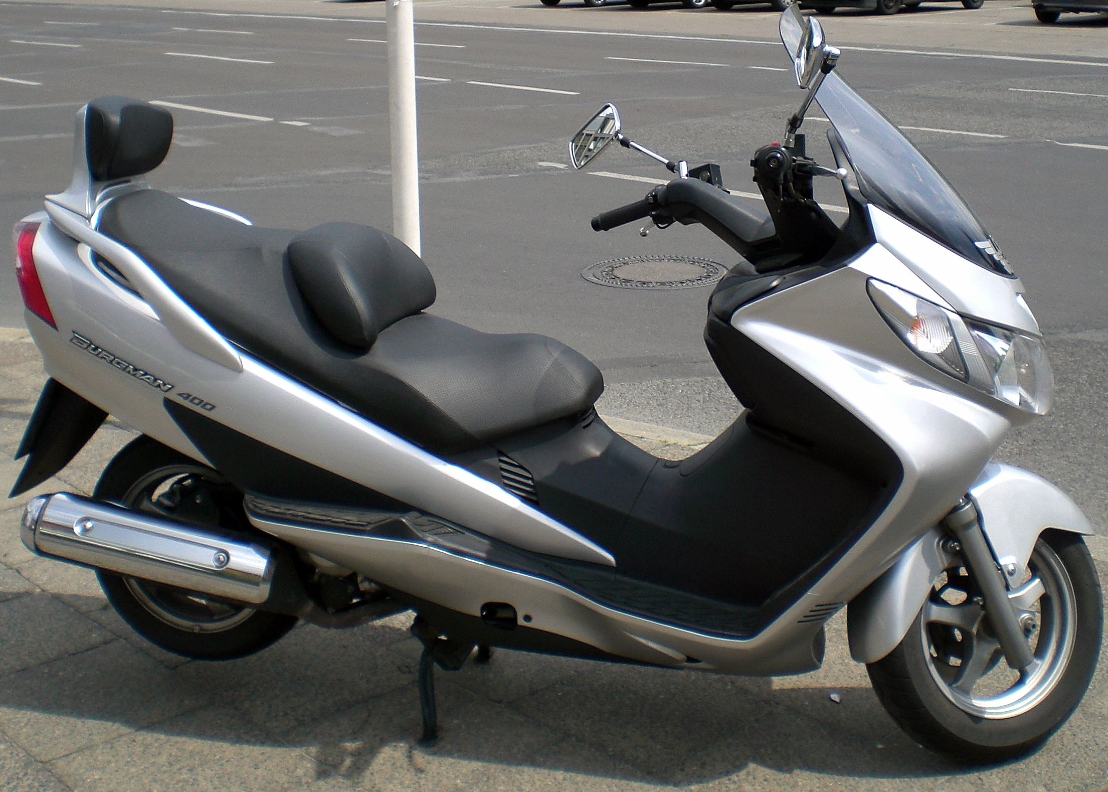
With this in mind I started looking for very big scooters or small motorcycles to use in a smaller version of the system shown in post 74. While 16” and 17” are the norm for rear motorcycle rims, a Honda CN250 “maxi-scooter” has 10” rims. More importantly it has a weight of 346 lbs with no riders and a top speed of 72 mph. Since most of the weight on a scooter is to the rear, even without a couple of passengers, it seems safe to say that tires capable of handling the needs of a 4-5 passenger, single bogie, highway speed-rated PRT vehicle are already on store shelves in sizes down to 10”. The smallest scooter wheel that I have found so far that is rated for 100 mph is the Burgman 400’s, at 13.”

There is more to this than using stock tires. There are the wheel bearings. Here I have to admit to being behind the times. Improving manufacturing techniques and material science continue to change the rules. It used to be that bearings for our application would need to be roller bearings, probably tapered, and that they would tend to overheat. I have just finished looking at a bunch of videos of motorcycle bearing replacement, (including the heavy, small wheeled but over 100 mph Burgman 650) and it looks like they are running on simple sealed ball bearings. Hmmm. Ceramic balls, super finished, super hard steel races… Onward and upward! The bottom line is this. The large wheel size that has driven in my track designs has always been a guideline more than a rule. It would now appear that off-the-shelf tires and ball bearings can be had that are designed for 2000 rpm, 450 lb. per wheel applications. Therefore there is little justification for a 36” high track, at least in town. What I am shooting for is a finished vehicle-plus-track height of 10’, without compromising speed or comfort. I would note, however, that existing products, like motorcycle bearings or tires, do not necessarily represent the last word in what can be done technologically. Just because there is currently no 9” 120 mph, 500 lb. tire doesn’t mean it would be difficult to make. I just would prefer not to base a track standard around it. My inclination at present is to go with a 10” rim, (16” outside diameter) even though there may not be any tires currently available which are rated for speeds over 72 mph. Sometime down the road…err … track, if PRT on this track standard ever takes off, someone will make such a tire. The same goes for motors. Nearly every manufacturer advertises that they will design and build to your specifications and needs. Still, a preliminary design needs to have some solid basis for its dimensions…
One other… another…. the.. zzzz zzzzzzzzzzz zzzzzz…..the  zzzzzzz……

Sunday, April 4, 2010

80> Twisted

I guess I have come up with a solution, of sorts, to the problem I posed in last week’s post. By introducing a rotating joint where the swing arm attaches to the cab, the cab can be pivoted sideways. This gives the clearance required for vertical travel. It also opens up some interesting station design options, such as the closely spaced front boarding shown in this video for Monic PRT.

 
The picture above shows the indoor station problem to scale. The rail here is fairly large, (nearly 36” tall) and is the high-speed design shown in post 74. The vehicle is 63” tall at the pivot point. This cannot be reduced much without making the seats too low or sacrificing headroom. (No, the rail is not part of the back wall; the viewing angle just makes it appear that way...)

The ceiling as shown is 10’ 9”. Luckily, most modern buildings have more distance than this between floors. That makes the bottom of the track at 7’9”, barely within reach of the average adult. Because being able to reach it at all is a bit troubling, work continues on trying to find the best way to shave a few inches off of that 36” dimension. 
 
In the second illustration the cab has been turned sideways to the track in preparation for descent and in the last it is shown on a vertical track section. Note that the swing arm must be at least half of the width of the cab, but not so long as to push the overall height of the system higher than is necessary to keep track out of easy reach, lest the system be too tall to fit between the floors of most buildings. 


One thing I would like to accomplish with these designs is to create a system architecture that enables a business model that is not as reliant on busy stations. I understand that previous designers have had to keep in mind that “the squeaky wheel gets the grease,” so any initial system is likely to be for a very busy area. Also, in the beginning, limited funding will mean that PRT will have to prove itself with a minimum of both track and stations. Still, PRT’s main strength lies in concept of point-to-point travel, and that means lots of stations. Trying to do otherwise is like having a taxi service that only goes to and from a few locations. We already have that; they’re called shuttles, and are most efficient when transporting larger groups.

Reducing the cost of the stations is a main factor favoring hanging vehicles over bottom-supported designs, which require extensive means to keep people away from the track, like elevators, gates, fences, etc. Cheaper stations will eventually pay off in higher ridership. Can you imagine, for instance, public buses trying to operate with two thirds of the bus stops removed? Who would want to walk that far, both before and after the ride, and presumably on the return trip as well? PRT is no different. It is unavoidable that initially PRT will have to start in an environment where shuttles would be competitive, but it is unwise to create a system architecture that is only economically viable in these situations. This is particularly true in many U.S. cities, where activities like shopping and entertainment are often done very far from the city center. By the way, the larger track size shown is fully compatible with larger group (GRT) vehicles, if it can be shown that they would be more effective in certain routes. The vertical or steep slope travel capability, however, is PRT only, and aimed primarily at situations where a small footprint is needed, yet the ridership isn’t sufficient to justify an elevator equipped station. Sharing space with a bus stop comes to mind. 

Finally, I have to acknowledge the differences with European hanging designs, which have no swing-arm at all, although they have similar track heights, because they tend to be taller, walk-in style vehicles. A quick “walking view” tour in Google Maps of various European city centers reveals huge masses of pedestrians compared to the U.S… many, many times more. I can certainly see that a lower speed, inner-city centric approach could make a lot of sense there. While we struggle with “urban renewal” projects here in the U.S., it appears that they’ve “been there, done that,” in Europe, perhaps hundreds of years ago! (Some of the oldest U.S. cities seem to have more vibrant downtowns as well, and being constrained by water seems to help somewhat.)  The whole structure of many American cities, especially in the fast growing “Sunbelt”, is about growth along freeways, giving the cities long tentacles of urbanization. The designs I have shown reflect this landscape.